I’ve decided to make the all of the titles of my posts completely boring. Sorry. Maybe I will feel a little more enthusiasm later in the post, but doubtful.
First order of business is that I built a rotisserie. I started thinking that I needed one last week. I wanted something that I could actually give the playfield some angle so that I could play a couple games if necessary. I threw a sketch together and sent it to Joe, and he mentioned I was an idiot for trying to do it myself. (My words, not his). He sent me a link of a well thought out rotisserie that only took about an hour to construct. What the posters didn’t mention is that you are going to spend about two hours at the local hardware store picking up all the materials, but that is mostly because I get to the nuts and bolts aisle and my eyes go all haywire. Here is the link that Joe sent me. https://pinside.com/pinball/forum/topic/vids-quick-and-dirty-rotisserie-guide. Fantastically simple to build, and it costs around $100 at today’s prices. You could easily cut the price by $20 or $30 if you are willing to cut the threads yourself.
Here’s the things I’ve learned building the rotisserie.
- Either use a monkey wrench, or at least use a lever in the pipes torque the pipes together as much as possible. I didn’t do that, and mine is wobbly. It will be better when I pull the playfield off it and tighten it up, but I was too excited to use it. (It was noted in the instructions, I just didn’t follow them).
- I’m going to add wood blocks to the pieces of angle metal that hold the playfield. Using blocks will allow me to adjust them to places on the playfield that have no components. Making them out of wood means that I can power the playfield and not worry about it shorting out to the metal rails. (I don’t think it was envisioned as powering it on the rotisserie, but since I only need a single 24 pin Molex power connector, it is very convenient for me to power it there. It also makes it easy solder on the back and hopefully debug issues.)
After finishing the rotisserie, it was on to powering the playfield. The end design uses the Raspberry Pi to turn the power supply on and off. It powers the solenoid boards/input boards with 5VSB from a PC power supply (which is always on). I tried powering it and just hard wiring the 48V power supply on. The problem is that it takes about 100 ms for the processors to come up and do power on self tests, and during that time, the FET inputs are floating. Not a problem in the real system, but it is annoying to hear the click at startup. I ended up hooking up a wall wart for the 5VSB supply so that I can plug in the wall wart, then turn on the big 48V supply.
After initially turning on the board, I immediately blew out the fuse that I had for the flippers. I’m missing something on how Game Plan configured their flippers. I assumed one thing, and evidently that was wrong because I blew the fuse. Spent a little time tonight debugging it, but didn’t get any closer. I had it working well for a little bit, but it wasn’t at full strength. As soon as I tried to make it at full strength I started having problems.
At one point last night, one of the solenoids started chattering. It could be that I had a ground loop, but I couldn’t reproduce it tonight. Originally the return to the wall wart had to go through the PC power supply to get back to ground. (Again, not what would happen in the real system, but right now I’m cobbling a little bit of stuff together.) I added a ground return line to the wall wart so ground would be connected properly.
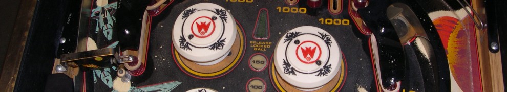
So here is the first video of firing the solenoids on Sharp Shooter 2. The pop bumpers sound really nice and crisp. The flippers are weak because how they were hooked up. I was only powering the hold coil of the flipper. http://youtu.be/5w517evHcOE.
I just looked up the resistance on the flipper coil. It is a 5008B and only has 1.2 ohms of resistance. No wonder the original machine could run off 24V. If that is the case I need to cut down the initial kick and hold significantly. I was running originally running at 48ms initial kick, and 25% sustain, but I’ll try cutting it down to 16ms initial kick and 6.25% sustain. That is definitely the strongest flipper coil I’ve ever seen.
