Category Archives: Sharp Shooter 2

Upgrade of Sharp Shooter 2 to new driver cards

4/24/2015, Measure how many times?

So the OPP team is getting really close to ordering the final playfield art.  Through my incompetence, this has taken more time than it should have.  Back in January when I had the top of the playfield disassembled, I should have printed out a template of where all the features were on the playfield and verified the positioning of the template.  Well, I did print it out, and looked at it, and said, hey, everything looks about right.  I didn’t take the time to really examine it and make sure everything was spot on.

So in the last two weeks there has been a huge push to finish the playfield art.  The art department (located at OPP mid-west headquarters) had to spend many a late night to get it done, and they came through.  The only problem is I printed out an art proof, and I suddenly realized that many of the inserts were off about .15 inches.  I realized the enormity of the situation around Monday of this week.  I also realized that the first template I printed back in January was not correct because FedEx printed it and shrunk one of the directions to fit on their printer without telling me.  That being said, if getting a printout from one of these places, insure that they don’t “help” you by shrinking it to fit.  The FedEx place that I use can comfortably make prints that are A1 size which is 23.4″x33.1″.  I allow at least 1/2 inch of margin around the edge for safety.  Last night I updated the template, and today I’ll get another printout to verify the newest template.  The art department has already been sent the template, so hopefully this will be the end of the debacle I caused.  The take away is to not rush things.  Spend the time to verify your playfield template even if it means that it will be another week or two until you build the playfield back up.  It will be worth it in the end and will end up taking less time.

So verifying the locations of the inserts was more difficult than expected.  I tried to use the method the Goonie’s guy did with a flashlight, and just could not get enough light to really tell the location of the inserts.  The method I found which worked best was the old 100 watt incandescent bulb in a desk lamp beneath the playfield.  I turned out all the lights in the room and it was suddenly very easy to verify the locations.  The lamp had to be moved a couple of times to get light at different spots in the playfield, but it made the verification really easy.  I then used a digital caliper to measure the offsets.

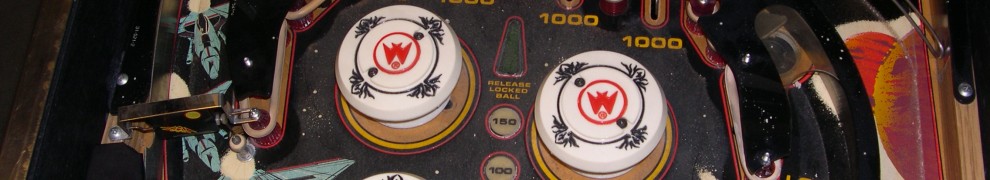
Here’s a couple pictures of the art with the offsets marked:

Playfield Lower Changes Playfield Upper Changes

Next up was updating the template.  My tool of choice is Gimp because it is open source.  I truly dislike the program, but every once in a while, it surprises by making something easy.  The menus are really non-intuitive to me, and I’m almost always certain that it could do something, but I just don’t know how to make it happen.

Here’s the Gimp process for modifying the template.  First create a new layer from the previous template layer.  Only view the one new layer, and highlight it so you are editing just that layer.  Now change the cursor to rectangular select by pressing the ‘r’ key.  Now for each part of the template you want to move:

  1. Draw a rectangular select region around just the piece that you want to move.
  2. shft-ctl-L, float the selection
  3. shft-ctl-O, offset floating layer.  (Change the units to inches, and change the edge behavior to “make transparent”.  Modify the x offset and the y offsets.
  4. ctl-h, anchor the floating layer
  5. Repeat the above steps for each item that needs to move.

That makes updating the template a breeze.  (It just took me 30 minutes of searching the web to figure out how to do it efficiently).

Much of the playfield is going to be painted white so that the vinyl overlay will look as good as possible.  The vinyl printers can’t print white reliably.  The options are to use an opaque overlay (the overlay is white vinyl and then the art is printed on top of that), do a second overlay that is simply a white backing layer where necessary, or to paint the playfield white where the wood grain should not show through.  The first option won’t work because the inserts would be too dark.  The second option would work, but doubles the cost of the overlay, and it would involve a lot of xacto knife work to get it right.  The last option seems the simplest to me.  If I get white paint on an insert, I can easily clean it off using paint thinner or water.  I’m planning on two layers of white, then another layer of clear to make sure that the vinyl overlay will adhere properly.

The OPP cabinet department has been hard at work on painting the black background paint on the cabinet.  That is completed, so just one more sanding, then applying a clear coat layer and the cabinet art can be installed.  Then it would be a rough sand and a couple of clear coat layers on top of that to make it rock solid.  I found that 600 grit sandpaper is the sweet spot for insuring the paint is smooth before applying the next layer.  I tried using 440 grit, but it removed too much material.

The OPP software department has finally started to work on the actual code for the machine.  They spent a good bit of time this week, and right now in simulation mode, the game starts, inlanes are rotating using flipper buttons, solenoids are getting reset, etc.  Having written out the rules in advance helps a lot so that the software department can quickly refer to them when questions arise as to what should happen when x gets hit.  There have been some minor updates to the rules documentation, but it is mostly clarifications.  The original version of rules looks like they were written by somebody that was watching TV at the same time as writing the pinball rules.  The second rev cleans up a lot of the language/grammar issues.

Here’s a quick link to the current rules.  All those attending Pintastic can study up to find the holes in the rules and use them to get the highest score possible.  It is saved as an .odt file (open document text).  RuleSheet


4/17/2015, So The Teardown Begins

New wordpress interface is giving me issues.  It keeps converting my posts into pages.  Grrr.  Stop it, I just want it to be a blog post.  I apologize if it sent out multiple emails to the one follower I have.

So I’ve played two or three “games” at this point.  A game is essentially as follows:  run the pinball framework which starts in attract mode, press the start button for as many players as you want in the game, the machine serves up the first ball, each switch scores you one point, when the ball drains either move to ball two or the second player, at the end of three balls go back to attract mode.  Truth be told that is all it does at this point.  I have verified all the switches are working, but there really aren’t any deeper rules at this point.

I have a bunch of cabinet stuff to do, so while I work on the cabinet, I can continue coding the rules.  The pinball framework has a debugger built into it where each of the switches can be simulated on the machine.  I don’t really need the physical pinball machine to program it with the simulator, so why not tear it apart.

Two weeks ago I took the cabinet apart and started working on finishing it.  I sanded everything down to bare wood on the base of the cabinet (why?  I could have just rough sanded it, and painted it black, but I didn’t realize that until too late.  Maybe sanding it down to wood will make it look better.)  Since then, I’ve got two coats finished and sanded in between.  I’m planning on at least one more coat of black, then a coat of clear before attaching the vinyl side art.  After that, probably one or two more coats of clear to protect the vinyl.

One of the riskiest things is the playfield art and insuring that it matches up perfectly with the playfield holes/inserts, etc.  This week, I decided to try and reduce risk by printing a copy of the newest playfield art, and verifying the position of each of the inserts.  I did a rough job of this before and moved some of the inserts slightly, but now I want to make sure it is absolutely perfect.  If the first order of the playfield art is exactly correct it will save a lot of time and significantly reduce the time before I can get the machine back together and start really play testing it.  I’m also going to verify every single post/hole in the playfield to make sure that the holes are easy to find when they are covered with the vinyl overlay.  The goal is to get the playfield overlay ordered by the end of this month.  Joe has essentially finished the art, it’s just waiting for me to re-verify the insert positions.

The speakers are finally mounted on the piece of plywood that I cut out so many months ago.  I have a beautiful pieced of pleather which should go with the whole western theme.  I would have like real leather, and to tool a design into it, but I don’t have time for that sort of project.  That might be one of the things that I can eventually update.

That is really all that is happening right now.  Things seem to be on track to get it finished which makes me happy.  When it goes to Pintastic, it isn’t going to be finished, but I’m hoping it will be very playable.

3/22/2015, Quick video update

Most of the point of this post is just to say I threw a new video up on youtube.  Some follow the OPP youtube feed, many don’t, so here’s the pointer to it.  I tried to turn the camera 90 degrees to get a better shot, but it looks atrocious on youtube when it rotates it.  I have to figure out a better way to take videos that show the backglass/LCD and the playfield.

The beginning of the video shows a short LED light show.  The camera angle really needed to be higher to see the insert lighting.  Multiple static  images are displayed on the backglass.   Both of these are controlled by using chaining.  The LEDs use an LED chain, while the images use an image or video chain.  This allows the programmer to focus on rules instead of blinking lights.  Sounds are also being played in a loop, but I don’t have the speakers hooked up yet.

Next in the video, the start button is pressed, and the first ball is served.  The skill shot insert is blinked rapidly.   (Again, nearly impossible to see in the video).  The ball is plunged, and scoring starts.  The left and right flippers rotate the inlanes to help the player complete the inlanes.

The ball eventually drains and the next two balls go similarly.  At the end of the last ball the machine resets and starts going through the attract mode again.  The last scores remain.

That pretty much proves out all the features needed to run a game.  The big pieces of work coding wise are creating the new rules.

The insert lights sometimes flicker when the solenoids fire.  This is partly due to the fact that I did part of the fix for LEDs, but didn’t have enough parts to finish it.  The rest of the parts should be coming in this week.

Double flipping still shorts out the power supply, but the parts necessary to correctly fix it should also be in that package.

A lot of updates to the repository in the last week.  Look at the commit comments if interested.

3/15/2015, Another two weeks, oh how quickly

Another two weeks have come and gone.  Things are moving quickly, but I wonder if they are moving quickly enough.  I guess time will tell.  We are now at less than four months until Pintastic New England.  I noted to one of my friends, “Well, there is no art.  I’ve never hooked it up to a computer to keep score.  There is no sound.  There is no backglass.  There is no front door on the machine.  I’ve never tried to run LED changes, rules, and serial comms at the same time.  You have to follow a very specific boot sequence or the power supplies will incorrectly detect a short.  Besides those minor things, I’m sure it’s almost done.  Yeah, no problem.”

So that being said, let’s look at what has been done in the last two weeks:

Pinball Framework:  Added support for updating multiple LED cards at once by passing list with a mask for each card, and set bits for each card.  Added parallel port processing to support updating the incandescent driver boards.  Updated solenoid kick command and tested.

Started writing actual code for SS3.  All eleven modes have been designed with four different difficulty levels.  There are also a couple side goals to try to get more  points.  It should be full featured enough for the show.

The LED update thread updates the LEDs every 100 ms.  I measured the timing for the update to occur by bit banging the parallel port and it averages 1.5 to 2 ms.  That is probably the most time consuming thing that the SS3 needs to do all the time, so I’m feeling good about it only taking 2% of the processor.

Part of the Pintastic New England contest is to present the final cost of the pinball machine.  This includes the price of the base machine, price of all the pieces added to the machine, and money spent.  Of course, the time put into the restoration is all under the table.  So here is a quick rundown of the costs so far, and what I see in the future:

  • Playfield, $75.  It was a populated playfield with plastics.  Everything was on the bottom.  Many of the drop targets were broken.  It included wiring, which I reused.
  • Cabinet, $50.  A Gottlieb Gladiators cabinet.  Completely different pinball manufacturer and the only “fitting” that I did was making sure that the playfield fit inside the cabinet.  I assumed everything else could be fixed.
  • Backbox, $30.  It is a secret service backbox.  It was a good buy because it contained extra light bulb holders that I could use to replace the broken ones on the playfield.
  • Driver/Input cards, $100.  These are OPP cards that I had made about two years ago.  The $100 also includes the connectors needed to connect to the cards.  The boards are through-hole, so I soldered them up myself.  These are the same cards that Joe and Cactus Jack are using.  Some of the FETs and connectors are too close to each other, but Joe actually came up with a great idea of mounting the FETs to the bottom of the board.  I just squeezed everything together which also works.
  • Power Supplies, $50.  Simple PC power supplies that are tied together.  Currently using four, but I’m probably going to drop that number down to three because many things are still too powerful.
  • Art, $150.  This assumes three orders from BannerBuzz.  I’ve already ordered the side cabinet art.  I expect to need two more orders from banner buzz because the inserts might not line up perfectly.  The cabinet side art was $80 because it is so much area, but it looks really nice.
  • LEDs/parts, $100.  Pinball life got a bunch of money for LED light bulbs.  That is the majority of the money.
  • LCD monitor, $80.  Originally it was going to be for the backpack pinball machine, but well, it was sitting in the basement, so now it is in this machine.  It fits the cabinet perfectly, so I’m happy with it.
  • Old PC, free.  My wife’s grandmother’s old PC that I built for her eight years ago.  It was too old, and she has a laptop now, so she sent it back to me.  I re-purposed it, and hope it is fast enough to run the pinball machine.
  • Lockdown bar, free.  Joe provided this since it was sitting around.  Thanks Joe.

So I’m expecting the total for the whole machine to be $635 at this point.  It is going to be interesting going into the restoration throwdown where some of the people threw in a CPR playfield which can be $700 or $800.  My guess is that the end machine, even with overruns will be a total of about $700.

So Friday morning, Google sends me an email that Google code repository is disappearing.  Github has finally taken over the world of open source.  Because of that I’ve moved the repository onto Source Forge for the time being.  I’ve already done the import, and will probably keep the two repositories in synch for the next six or eight months.  At that point, I will stop updating the Google code repository and let it die.  The source forge repository is located at http://sourceforge.net/p/open-pinball-project.  I may eventually move it to Github.

I’ve been running a lot of tests with the incandescent boards, and what I thought was fixed, still has issues.  After running different patterns on the boards, it turns out that I’m not getting clean signals on the data lines going between the cards.  A single walking 0 works, or a single walking 1 works because there is only one data transition.  A pattern of 0x55 or 0xaa causes issues and gets flickering to occur.  The only signals that can have that effect is the data lines between the boards.  Simply put a series termination resistor in there and the problem will be fixed.  Bummer is that I don’t have any low value resistors sitting around.  Grrrrr.

I was going to do a video, but just don’t have time.  I’m pretty close to a breakthrough video, that I’m going to wait for a little bit more before tossing up the next video.  It would be nice to have a good video of the framework running, with sound, etc.  Another couple of weeks and all that should be happening.


2/28/2015, Lights, Camera, Action

In the last three weeks, some major pieces of work have been completed and a lot of little things.

I was having some issues reliably communicating with the incandescent cards.  My original interface card between the parallel port and the incandescent boards used simple FETs to convert from 3.3V to 5V.  When I sent the interface card to Cactus Jack, I made him an interface card using a 3.3V to 5V driver chip.  The problem with using the straight FETs is that the slew rate is very fast, and I was getting a lot of reflections on the signal lines.  I had a couple of extra driver interface chips around and built up a card.  As soon as I installed that card, the light bulbs immediately started working reliably.  I’ll eventually create a Kicad version of the card that will also be combined with the RS232 interface card.

Spent a good amount of time finishing up mounting the playfield in the correct position, making a plate to mount the shooter rod, etc.  After remounting the lockdown bar to the correct position, the playfield now easily falls into position, and the shooter bar now lines up properly.  One more mechanical fear removed.

All the incandescent bulbs have now been replaced with LED bulbs.  The warm white three LED bulbs from Pinball Life seem yellow to me.  I was expecting a slightly different color, but I’ve grown used to the color.

Spent some time just at the end of the week starting to work on the rules.  Nothing big happening yet, but just starting to write the code.  The code for the coin drop was ripped out because the machine will be on free play.  I’m expecting to only have the eleven modes completed.  I don’t think that I’m going to be able to get multi-ball to work by Pintastic.  The main problem is that I don’t know how to hook up a second switch, so I can detect when both balls are in the drain.

So I’m officially declaring it four months until Pintastic New England.  (Pintastic is actually on the 11th of July, but close enough.)  I only calculated it this week, and was completely surprised that it is only four months, and not six months until July.  Doh!  I better get crack-a-lackin.  The one nice part is that all of the electronic hardware is tested.  That means most of the stuff is coding, and adding artwork.  It is going to be a lot of work, but it looks like it is possible to make it.

Because of time constraints, I’m starting to drop out unnecessary nice to haves.  I was planning on doing new plastics, but since the plastics are in good shape, I’m expecting to re-use the existing ones.

I’m declaring that the machine will hopefully as good as a NIB Stern machine.  As everyone knows, Stern typically tosses out machines with far from finished code.  By July I’m hoping to have SS3 playing well enough to have fun for the casual player, but won’t have the depth of rules that I’m currently expecting in the end.  A lot of time has to be spent on getting the physical outside of the machine and playfield ready, and that is going to have to take precedence over having a set of rules that you can spend months trying to master.

Here is a quick video of the current progress:

2/9/2015 – GenPyCode and PinballFramework

The Frankenstein Sharpe Shooter 3 machine is slowly coming alive.  Stealing parts from multiple types and multiple brands of machines is starting to make things difficult for me.  The lockdown bar didn’t quite fit properly, so I needed to modify it a little bit.  That has been completed, but then adding the shooter rod, it seems that Gameplan used a different length of shooter rod than Williams.  (Why???).  I mounted the lockdown bar a little too low in the cabinet, so now I’m going to have to remount it about 1/4 inch higher.  (The good part of that is that I can now mount the flipper buttons, and stop using an electrical junction box to press the flippers).

I stole most of the “rules” running in the game from Joe’s Blue October demo I did over a year ago.  That uses coin drops and presses of the start button to start a game.  Ooop, I don’t have either of those switches hooked up, so I can’t start the game at this point.  Little things like that keep popping up like moles and you just have to keep knocking them down.

A lot of time has been put into GenPyCode the last few weeks. For that one person that is actually reading this and has not been following, the GenPyCode Python program takes a rules file and converts it into Python classes that are then run using the PinballFramework. It takes much of the grunt work out of creating the necessary classes to run the individual pinball machine rules.

I’ll eventually write up a document on the rules file, but a lot of it is self explanatory.  The solenoid section describes how many solenoid cards are in the system and their configurations.  The input cards (switch inputs) section describes the number of switch input cards and their configurations.

GenPyCode is now passed a parameter with the output directory to put the generated files.  In my case, the command line used is:

python GenPyCode.py -rulesFile=ss3rules.txt -outDir=SS3

This uses the ss3rules.txt input file and stores the output in the SS3 directory.  Previously, the generator always used the same output directory and input file name, but it is useful to be able to work on rules for multiple machines at the same time.

The files in the SS3 directory are then moved into the PinballFramework directory to be run by the pinball machine.  The pinball framework has been modified to support multiple rulesets.  Here is my current command line for the pinball framework and SS3:

python PinballFramework.py -port=COM1 -simWidth=854 -debug -rulesDir=SS3

-port=xxxxx Lists the serial port used by the solenoid/input cards.  If this parameter is blank or does not exist, the framework will disable serial communications.  This is very useful since I’m not sitting at the pinball machine most of the time when I’m writing the rules.  Instead, I’m simply simulating the switch inputs, etc.

-simWidth=854 Simulation width of the screen.  The pinball machine runs in full screen mode, which makes it nearly impossible to develop.  Using the simWidth parameter, the LCD screen is scaled down, and a menubar is added so that it can easily be moved around.

-debug Creates the debug window which contains all of the solenoids, input switches and LEDs.  By pressing buttons in the debug window, switch inputs and solenoid inputs can be simulated.  The one problem with the debug window is that it does not have a scrollbar on the side.  SS3 has 2 solenoid cards, 2 switch input cards and 6 LED driver boards.  The debug window is too tall, and the bottom LED boards can’t be seen.  That’s probably going to be the next thing that I fix.

-rulesDir=yyyyy Directory location of the GenPyCode generated files.  It also contains the rulesFunc.py which fills out the logic for the game.  (The generator creates an empty shell for this file called rulesFunc.py.gen).

Joe gave me a bunch of great LCD screenshots which have been integrated into the attract mode on the backpanel.  In attract mode it cycles through the images which is really the first time “rules” are being run on the machine.

Lightbulbs are now brighter than I was expecting.  I’m guessing that I was shorting a 5V to ground through the rotisserie.  (There were a bunch of bulb sockets that were very close to the angle aluminum of the rotisserie.  I thought I threw enough non-conductive foam in there to isolate it, but it seems like I didn’t).  I put the playfield into the cabinet and lit it up using incandescent bulbs and it looks spectacular (in an early 80s sort of a way).  I now believe my calculations that 5VDC on incandescent bulbs are brighter than 6.3VAC on the bulbs which is what the math says.  The LED bulbs are still going to be great in the inserts to make those really pop.  (The mode inserts are a really dark purplish color which is going to mask a lot of the light).

There is a flipper issue when double flippering.  It is drawing too much currrent and shutting down one of the power supplies.  I believe that I have a fix, but don’t have the parts to make it happen.  I need to make a mouser order and get the stuff needed to fix that.

Next up is working on the getting all the lights firing as expected.  That will make the attract mode that much more exciting.  The LED functions also need to have better support for multiple cards.  (Right now they support only four cards, but since SS3 has six LED cards in it, the passed parameters need to move from a single parameter to passing in lists.)

1/19/2015, Backboxes, Playfields and Screens, oh, my!

A couple weekends ago, I finished populating the playfield.  While not a Herculean task, it was a little bit annoying since I filled all post holes because they were almost all pulling out and not holding properly.   After the clearcoat, I used a nail to punch the center of the bamboo skewer, than a small drill bit to drill the pilot hole.  It went surprisingly well, and I’m now happy to report that the playfield is probably in better shape than it has been for 15 years.  Here is a quick picture of the populated playfield.

WhiteWood

I decided I wasn’t going to fire up the playfield again until I got the backbox in better shape.  A couple weeks back I installed the power supplies, and the MaxPower card that creates my 48V.  (On a side note, Joe just bought a 48V power supply for dirt cheap (around $20 or $25 with shipping).  Maybe the time of creating your own power supply from multiple PC power supplies is over.  That being said, I will not miss it.  Doing it that way requires a lot of extra wires which most of them are unused.)  The four PC power supplies take up the top 1/5 of the backbox.  The MaxPower board takes up a small amount of space just below them.

I was handed back a small form factor PC (mini-ITX based card) that was no longer wanted.  I had that sitting on the side running windows XP, but it was cumbersome to move that around with all its extra stuff.  I decided to rip that apart and also mount that stuff in the backbox.  That includes another PC power supply, the mini-ITX motherboard, and a hard disk drive.  All of that stuff will be removed and replaced with a single Raspberry Pi eventually.

I mounted a speaker panel which also allows the bottom half of the monitor to show through.  The top half of the monitor is going to be behind the backglass and will have a transparent window in the backglass so that I can display images.

I’m having troubles mounting the monitor, but I’m trying to spend a good amount of time to get it right, so that it can easily be removed for “servicing.”  That involves building a bracket of some sort out of metal.  I have the metal left over from the ground that was in the back of the backbox.  Plenty of metal, but I need to make clean 90 degree bends with a good degree of accuracy.  I don’t own a metal brake, so I’m being very cautious.  Here are a couple of pictures of backbox, and backbox without the monitor.

GE GE

Last thing that I spent a good amount of time on these last few weeks is adding to the pinball framework or more specifically to the GenPyCode program.  That takes the rules.txt and generates Python files that are used by the pinball framework.  The generation of all the files except one is complete at this point.  For details look at the Subversion repository check-in.  Within the next week or two, I should have that completed and should be back to being able to start working on the actual rules of the machine.

I have not finished wiring the GI, and it is simply a couple hours of work that I need to do.  Since the lights were so dim, I didn’t feel like bothering, but now with the LED bulbs, I’m hoping to get back to that.  I need to start working on putting the playfield in the cabinet, but that is only after all the wiring is done.

It’s been a busy couple of weeks, but things are moving quickly.  It’s amazing how quickly two weeks goes by, and that deadline of the beginning of July is looming ever closer.

1/6/2015 Backbox, Cabinet, etc

It’s been a busy couple of weeks here at the OPP.   This entry is going to be pretty scattered and I apologize.  Changes are happening to the playfield, cabinet, backbox, and pinball framework.

I’m working on the backbox during the time that I have to wait for the playfield to cure.  Last layer of polyurethane was on 12/27/2014.  Final top coats are normally supposed to be cure for 3 months, but since the playfield is going to be covered again, I’m hoping waiting 3 or 4 weeks is sufficient.

I picked up a backbox on Monday (12/29/2014).  After taking some measurements, I am much more excited.  Right now, if you look at previous pictures of the power supplies, they are all mounted on a piece of plywood.  That isn’t a good long term solution.  After turning on the supplies to see which direction the fan blows and taking some measurements, I’ve found I can mount them at the top of the backbox.  That will exhaust the heat out of the top of the back box as efficiently as possible.  The remaining 2/3 towards the bottom can mount the speakers, amplifier, main controller (aka Raspberry Pi, or mini-ITX board), Max Power board, monitor, etc.  I’m still thinking about how I’m going to mount the LCD screen, but my current thoughts are to use the EMI shielding metal from the original backbox and form some metal brackets that flare out larger than the monitor for easy access.

On the amplifier and speakers, I’ve decided I’m way too lazy to figure out anything for myself.  Because of that, I ended up just following Joe’s lead.  For Christmas, Santa brought me a Lepai amplifier (LP-2020A+) and Lanzai speakers (MX53). The amplifier can be powered using a 12V supply, so that will be connected to the Max Power board which can provide 12V.  Sweet. One less thing that needs to be plugged into AC power.  The controller can also turn the amplifier on/off by enabling/disabling the PC power supply voltages.

Finished my big order to pinball life last week.  It includes all the LED bulbs.  The bulbs cost $57.  The playfield was only $75.  Hmmmm.   I would not have guessed that I would be spending that much money on bulbs, but if it achieves the look that I’m hoping, it will be well worth the price of admission.  The order also contained all the little annoying parts that I was missing:  new posts since many of them are broken or chipped, leg levelers, leg brackets (cabinet didn’t have any brackets on the front), and plastic channel for the playfield glass.  I tried a couple of places to find cheaper parts, and pinball life definitely seemed to have best price/selection.  This is my first order from them, so we will see how they do.  I was hoping this would be the last major order, and the day after ordering, I realize that I don’t have a start button.  That is easy enough to dummy up, but I’m annoyed I didn’t notice it earlier.

Joe is sending me a lockdown bar and a couple other random cabinet parts, so that I can install the playfield into the cabinet.  That’s a pretty big step for the project.

Started re-installing the top playfield parts.  The only annoying thing is that they all have to  be stripped off again to install the final artwork on the playfield.  Of course there is no playfield artwork, but somebody has offered to help.  It is going to be a heck of a lot better than anything that I can do.  I worked two or three days on some cabinet artwork, and in an hour, he threw something at me that was significantly better than what I did.  It once again proves how crappy I am at artwork.

The pinball machine has been entered in a contest.  This gives me a hard end date (7/10/2015- 7/11/2015), and forces me to hopefully get something fully working by early July.  The machine is entered in the Restoration Throwdown Contest (RTC) at the Pintastic New England show.  Here’s the link.  This is the first New England pinball show for quite a  few years and I’m very happy to see somebody getting a show up and running so close to home.  It will be interesting if people consider the Sharpe Shooter III a restoration, or something else.

I was going to hold the post off for a few pictures, but I can add more photos next update.  Seems like there is enough info, and I hate when the information gets too stale.

12/27/2014, Clearcoated playfield

The days before Christmas, I took time to fill in most of the post holes. Many of the holes could not hold the post studs anymore because they were stripped. The holes for the guides were also too large. Sometimes larger screws were used instead of the original screws. I’m going to change the studs back to the correct size, so that involved filling the playfield holes.  Some of the holes were so stripped they required two skewers to fill the hole.  I will end up drilling a pilot for each filled post hole to make sure that the post is at the correct position.

I ended up picking the bamboo skewers and glue method. I took a bamboo skewer, dipped it in some wood glue, then jammed it in the hole. After the glue dried, I used dikes (diagonal pliers) to cut off the extra skewer. Next, I used an exacto knife to make it flush with the playfield and get it ready for sanding.  Here’s a quick picture of the acupuncture playfield.

GE

The days around Christmas gave me some time to work on the playfield.  You may remember in the last few pictures that the playfield had the old art. I spent a couple quality hours with the orbital sander to remove the old art and create the “white wood”.  I ended up using 180 grit sandpaper to remove the artwork, and moving up to 220 grit sandpaper for the final smooth coat.  I purchased some 600 grit sandpaper, but since this is a a sublayer under the eventual mylar, it didn’t seem worth it.

After finishing the sanding, I used masking tape to mask off all the holes/light sockets in the playfield.  Polyurethane isn’t conductive, so it will destroy all the lamp sockets that it coats.  After masking off all the holes in the playfield, I wiped the playfield down with a rag, then wiped it down with some mineral spirits.  Let that dry and did a second wipe down.

The weather outside was over 50 degrees, so I could spray polyurethane outside and avoid the fumes.  I used four coats.  The first coat soaked into the wood as expected, the second coat soaked in a little bit, in a few areas, but most of it provided good coverage.  The third and fourth coats provided perfect good smooth coats.  The playfield stayed outside for a few hours to out gas.  Here’s a quick picture of the current playfield.

Clearcoat

I started looking for a backbox.  Sarah had some but they were too expensive for what I needed.  I just got in contact with K’s Arcade, and they think they might have some good candidates.  Hopefully I can also pick up the few remaining parts that I need.  That includes stuff like a lockdown bar, the plate that the lockdown bar locks into, a couple of flipper buttons, etc.  Mostly little bits that I haven’t picked up yet.

Next up will be putting the playfield back together.  Making a big order from Pinball Life for LED bulbs and some other random playfield parts that are broken and the parts I can’t scrounge from somewhere else.  I’m hoping to get the playfield into the cabinet by the end of January, but end of February is more realistic.

To finish the art, the top playfield parts will need to be removed again, and mylar added, and recoated with clearcoat, but that is many months away.  I still do not have any idea how I’m going to create the art on the playfield.   I have a couple ideas for art on the cabinet and backbox.

After the playfield is back together, and in the cabinet, I can start programming the rules.  That will involve finishing the framework, and hand coding all of the functions.  I’m not going to take the time to have the auto-generator to create the function code.  While that is a cool idea, I’m not sure how many people would use it, or if people would simply hand code the rules so they have more control of the machine.

12/14/2014, Video of Light Show

Finished some wiring today, and dragged an old computer down to run the lights.  I wanted to be able to have the old computer sitting down there so it didn’t need to set it up and torn down each time.

I wired in a PC power supply, and grabbed the 5V to power the lights.  It also uses the 12V for turning the FETs on and off.  There were a couple of light bulbs out, but since the whole thing is going to use LEDs, I didn’t feel like spending the time to change the bad bulbs.  Strangely, when I look back at my last post, I was pretty certain that I wasn’t going to work on the wiring.  Turned out it was low hanging fruit that needed to be done, and I had bought more crimps, so it made it pretty simple.  Here is a link to the video.  The blinking lights are slowed using a 100 ms sleep so the lights don’t blink too quickly.  I turned the basement lights off which is why the video is grainy.

The 5V from the power supply definitely doesn’t have enough ummph to run the mixture of 44 and 47 bulbs.  The playfield has about 50 bulbs, and when trying to run all of them, the bulbs get really dim.  Looking back at the bulb measurements I did, a 44 is 220 mA, a 47 is 136 mA, while a 4 SMD LED bulb is about 30 mA.

The test worked well enough, that I’m probably just going to tear down the setup and start working on the top side of the playfield and the cabinet.  Both need to be sanded down so art can be applied.